This is the new book I published in 2017 by Apress, Springer to introduce the use of OpenCV in Processing with a custom library I developed.
Check out more details at the Apress website.

This is the new book I published in 2017 by Apress, Springer to introduce the use of OpenCV in Processing with a custom library I developed.
Check out more details at the Apress website.
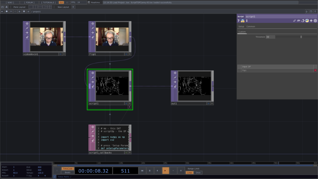
After the first introduction of the Script TOP, the coming example will implement the Canny Edge Detector with OpenCV in TouchDesigner as a demonstration. TouchDesigner already includes its own Edge TOP for edge detection and visualisation.

We also implement a slider parameter Threshold in the Script TOP to control the variation of edge detection.

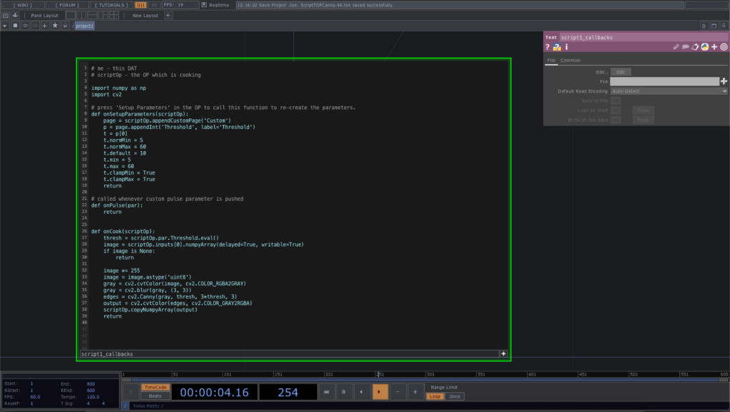
Here is the source code of the Script TOP. Note that we have made a lot of changes in the default function, onSetupParameters to include a custom parameter, Threshold as an integer slider. It will generate a value between 5 and 60, to be used in the onCook function as a threshold value for the Canny edge detection.
# me - this DAT
# scriptOp - the OP which is cooking
import numpy as np
import cv2
# press 'Setup Parameters' in the OP to call this function to re-create the parameters.
def onSetupParameters(scriptOp):
    page = scriptOp.appendCustomPage('Custom')
    p = page.appendInt('Threshold', label='Threshold')
    t = p[0]
    t.normMin = 5
    t.normMax = 60
    t.default = 10
    t.min = 5
    t.max = 60
    t.clampMin = True
    t.clampMax = True
    return

# called whenever custom pulse parameter is pushed
def onPulse(par):
    return

def onCook(scriptOp):
    thresh = scriptOp.par.Threshold.eval()
    image = scriptOp.inputs[0].numpyArray(delayed=True, writable=True)
    if image is None:
        return

    image *= 255
    image = image.astype('uint8')
    gray = cv2.cvtColor(image, cv2.COLOR_RGBA2GRAY)
    gray = cv2.blur(gray, (3, 3))
    edges = cv2.Canny(gray, thresh, 3*thresh, 3)
    output = cv2.cvtColor(edges, cv2.COLOR_GRAY2RGBA)
    scriptOp.copyNumpyArray(output)
    return
The first line in the onCook function is to retrieve the integer value from the parameter, Threshold. We also exit the function when there is not valid video image coming in. For the edge detection, we convert the RGBA image into grayscale and then perform a blur function. the cv2.Canny function returns the detected edges in a grayscale image, edges. Finally, we convert the edges into a regular RGBA image, output, for subsequent output as before.
The final TouchDesign project is available in this GitHub repository.
With the introduction of the new OpenCV 4.4.0, I updated the Processing library CVImage to the latest version of OpenCV. In this version, I take out the support for Linux and the contributed library optflow.
OpenCV 4.0.0 is now available in the official OpenCV.org website. I have compiled and packaged the CVImage library from my book together with the Java build of the new OpenCV library.
You can download the CVImage library here.
This is my first try of the p5.js together with the official release of OpenCV JavaScript. I decided not to use any browsers and experimented with the integration in the Electron environment with Node.js. The first experiment is a simple image processing application using Canny edge detector. The IDE I choose to work on is the free Visual Studio Code and which is also available in multiple OS platforms. I have tested both in Windows 10 and Mac OSX Mojave. In Mac OSX, I first install the Node.js with Homebrew.
brew update brew install node |
Then I install the Electron as a global package with npm.
npm install -g electron |
For the Visual Studio Code, I also include the JavaScript support and the ESLint plugin. The next step is to download the p5.js and p5.dom.js code from the p5.js website to your local folder. I put them into a libs folder outside of my application folders. For OpenCV, it actually includes the pre-built opencv.js from its documentation repository. The version I used here is 3.4.3. The only documentation I can find for OpenCV JS is this tutorial.
For each of the Node.js application, you can initialise it with the following command in its folder. Alternately, you can also do it within the Terminal window from Visual Studio Code. Fill in the details when prompted.
npm init |
In Visual Studio Code, you have to add a configuration to use the electron command to run the main program, main.js, rather than using the default node command. After adding the configuration, it will generate the launch.json file like the following,
{ // Use IntelliSense to learn about possible attributes. // Hover to view descriptions of existing attributes. // For more information, visit: https://go.microsoft.com/fwlink/?linkid=830387 "version": "0.2.0", "configurations": [ { "type": "node", "request": "launch", "name": "Electron Main", "runtimeExecutable": "electron", "program": "${workspaceFolder}/main.js", "protocol": "inspector" } ] } |
For the programming part, I used a main.js to define the Electron window and its related functions. The window will load the index.html page. It is the main webpage for the application. It will then call the sketch.js to perform the p5.js and OpenCV core functions. The p5.js and OpenCV communicate through the use of the canvas object. The GUI functions, imread() and imshow() are used for such communication. This example will switch on the default webcam to capture the live video and perform a blur and Canny edge detection.
Source code is now available at my GitHub repository.
The example is the Processing implementation of the OpenCV sample, fast_neural_style.py to work with live style transfer using existing pre-trained Torch models.
The complete source code is in my GitHub repository of this website at ml20180827a.
Referring back to the post on face landmark detection, the command to retrieve face landmark information is
fm.fit(im.getBGR(), faces, shapes); |
where im.getBGR() is the Mat variable of the input image; faces is the MatOfRect variable (a number of Rect) obtained from the face detection; shapes is the ArrayList<MatOfPoint2f> variable returning the face landmark details for each face detected.
Each face is a MatOfPoint2f value. We can convert it to an array of Point. The array has length 68. Each point in the array corresponds to a face landmark feature point in the face as shown in the below image.

To enhance the last post in face swap, we can make use of the cloning features of the Photo module in OpenCV. The command we use is the seamlessClone() function.
Photo.seamlessClone(warp, im2, mask, centre, output, Photo.NORMAL_CLONE); |
where warp is the accumulation of all warped triangles; im2 is the original target image; mask is the masked image of the convex hull of the face contour; centre is a Point variable of the centre of the target image; output will be the blended final image.
Complete source code is now in the GitHub repository, ml20180820b.
After the previous 4 exercises, we can start to work on with the OpenCV face swap example in Processing. With the two images, we first compute the face landmark for each of them. We then prepare the Delaunay triangulation for the 2nd image. Based on the triangles in the 2nd image, we find corresponding vertices in the 1st image. For each triangle pair, we perform the warp affine transform from the 1st image to the 2nd image. It will create the face swap effect.
Note the skin tone discrepancy in the 3rd image for the face swap.
Full source code is now available at the GitHub repository ml20180820a.